What is APVCam?
APVCam is a two-axis (pan and roll) motion control system designed for precise and repeatable video feedback. It is one of the parts of the APVFeedBakE system.
APVCam MOVEMENT & CAMERA
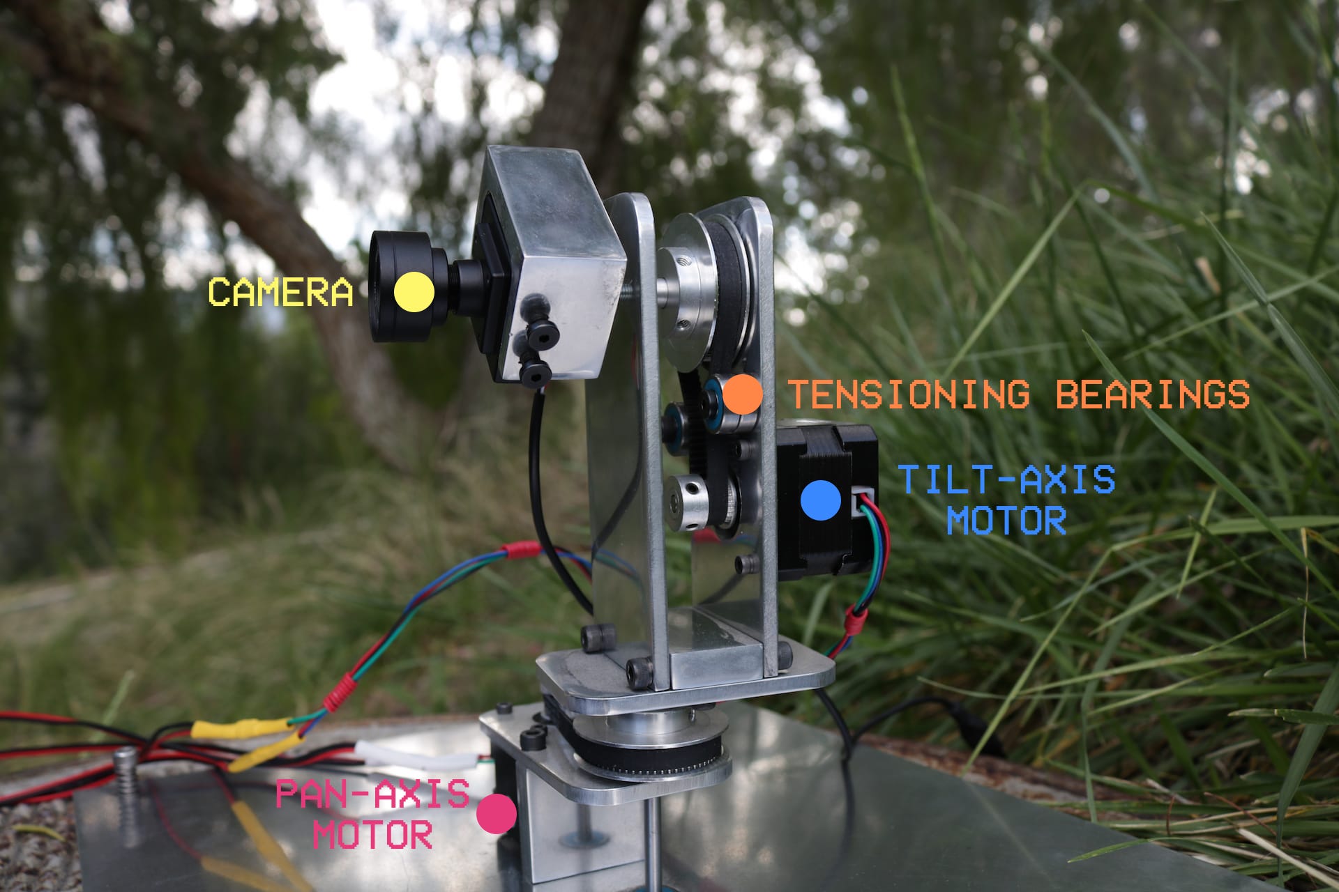
The APVCam uses two NEMA-17 Stepper Motors to provide users very precise positioning and movement on the pan and roll axes of the camera used for video feedback. The camera used in APVCam is a small and lightweight security camera normally used for CCTV applications. I chose this kind of camera because of its size, cheapness and ability to directly output composite video.
The camera requires only 12V power to function, and directly outputs NTSC composite video. It however has a fixed focusing distance, and requires subjects to be at a particular distance to be properly in focus.
The wires carrying power and video to and from the camera are not routed in such a way that allows continuous rotation. One mechanism that can be used to implement continuous rotation is the slip ring - an electromechanical device that allows the transmission of power and electrical signals from a stationary to a rotating structure.
CONTROL CIRCUITRY AND SOFTWARE
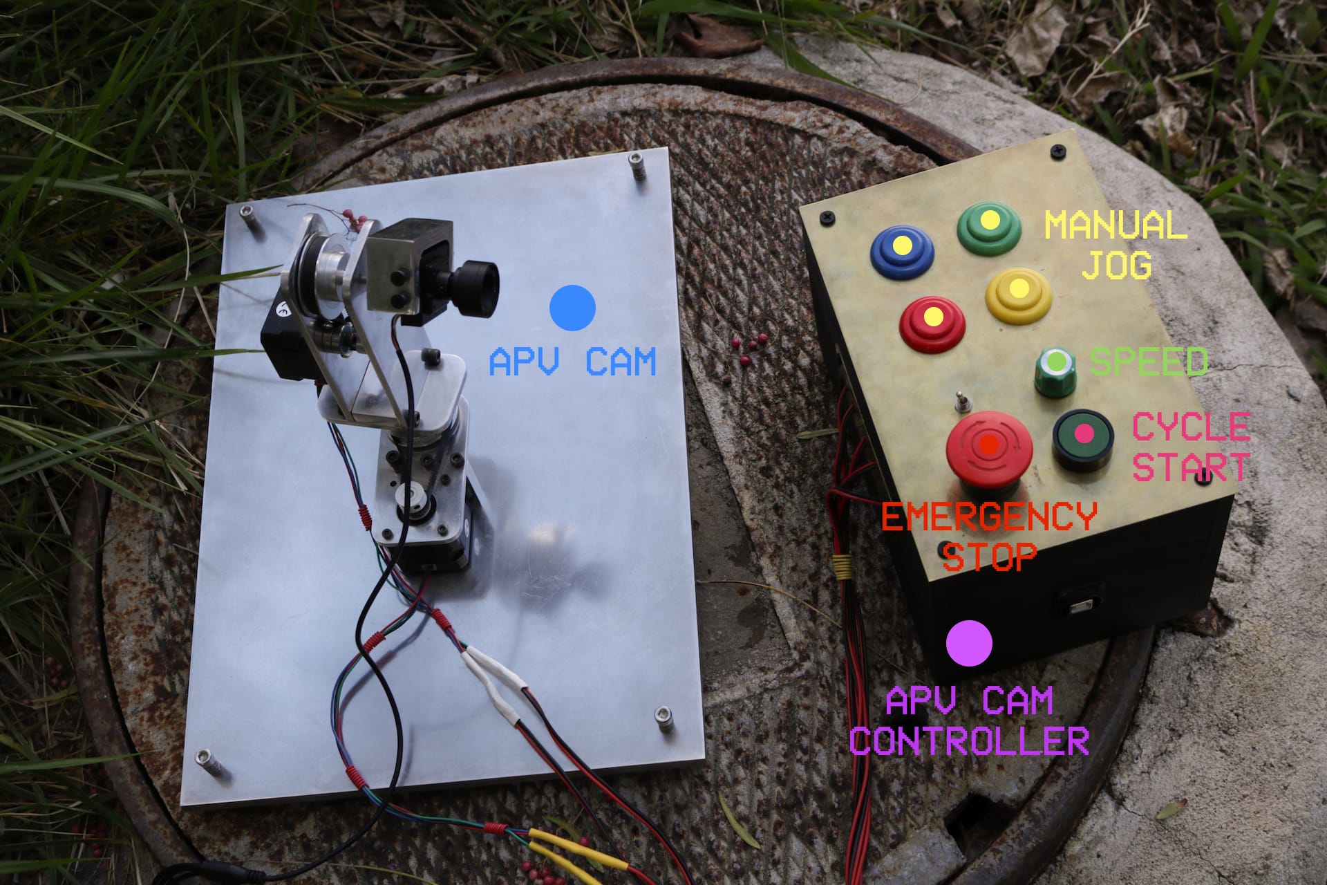
To control the APVCam, I built up some simple control circuitry - a few momentary buttons for manual jog, an assignable cycle start button, switch and a knob. APVCam’s controller is built using Arduino, with motor control duties handled by the Adafruit Motor Shield V2. All of this control circuitry is housed in the APV Cam Controller (pictured below)
ENGINEERING AND MACHINING
The power transmission system used to power the pan and roll axes of APVCam is a GT2 toothed belt and sprockets. The stepper motors are fitted with a 10 tooth sprocket and the drive shaft is fitted with a 30 tooth sprocket, providing a 3 to 1 mechanical advantage to increase torque and positioning accuracy.
The belt used is a closed loop of GT2 toothed belt, and the sprockets are spaced such that the belt is not at full operating tension. This allows for the belt to be put on much more easily, without having to remove either sprocket from its shaft. To adjust the tensioning of the belt, I added a pair of idler bearings which are held in place by a 10-32 UNF screw. There a number of tapped holes at different distances to allow for adjustability in the belt tension.
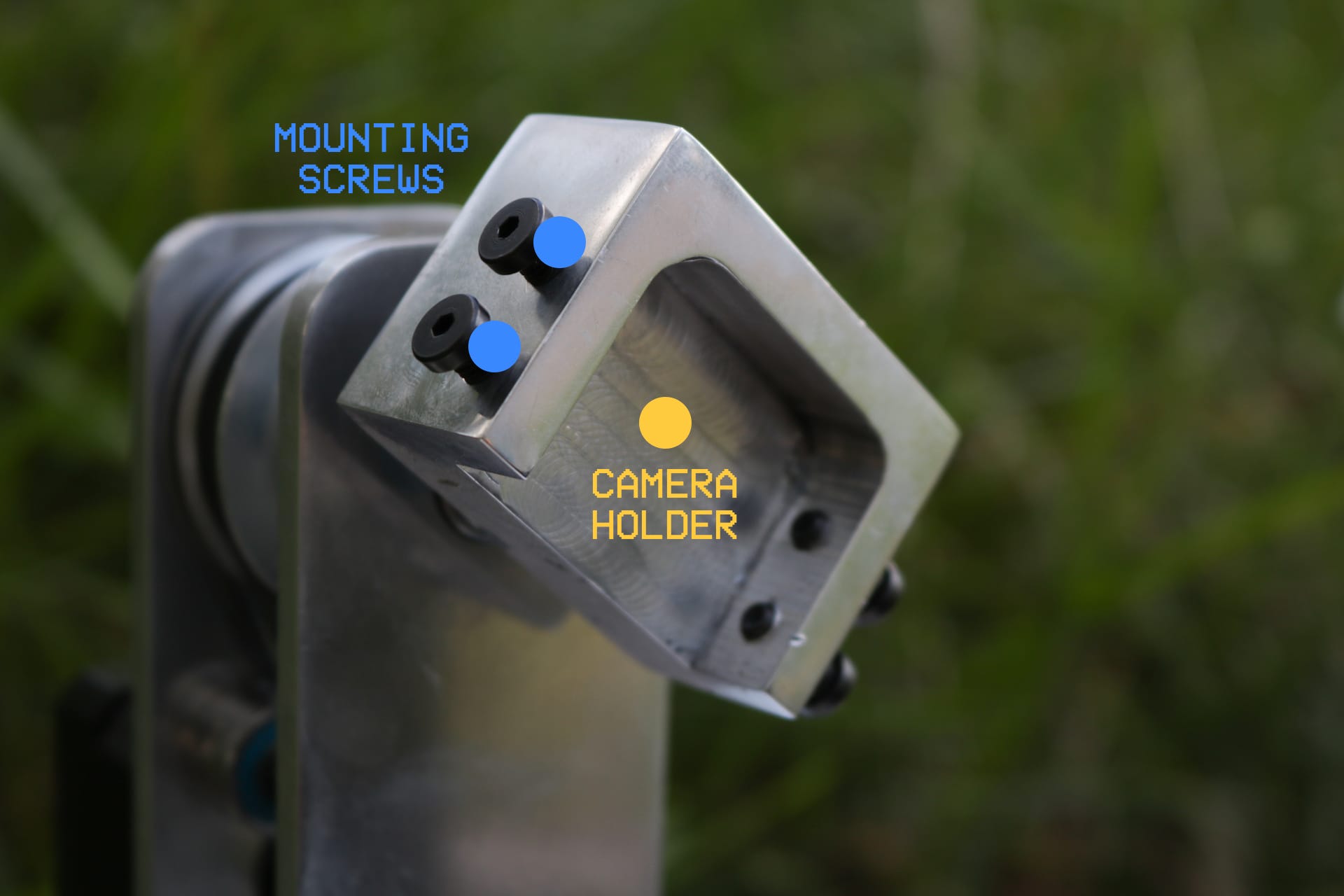
All of the parts for APVCam are machined from 6061 aluminium. Pictured below is the APVCam camera holder, which uses four 10-32 UNF screws to securely hold the camera and to center the camera on APVCam's roll axis. This camera centering system is inspired by the jaws of a 4 jaw chuck on a lathe. Having the ability to center the camera's lens axis to be concentric with the center of APVCam's roll axis allows for very interesting kaleidoscopic feedback effects.
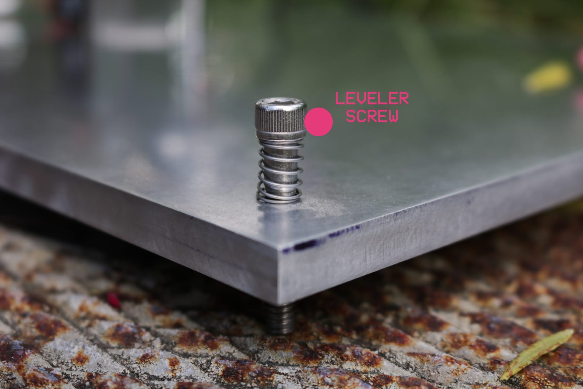
Each corner of the baseplate of APVCam has been drilled and tapped for 10-32 UNF fasteners, which are used as leveling screws to align APVCam to the plane of its subject. The leveler screws are preloaded by springs for stability. These allow for some adjustability to level or tilt the whole mechanism as needed.