WARNING!!!
Opening and modifying a Cathode Ray Tube (CRT) Television is an extremely dangerous process. CRTs can store charge for months and sometimes even years after they have been unplugged. Please exercise extreme caution and working on a CRT. This is NOT a step by step guide to making modifications to a CRT Television. If you have no prior experience with opening or operating on a CRT, please do not use this as a guide. I have provided links to other resources at the end of this page that provide an introductory explanation of the parts of a CRT TV, and CRT related safety.
Safety Procedures
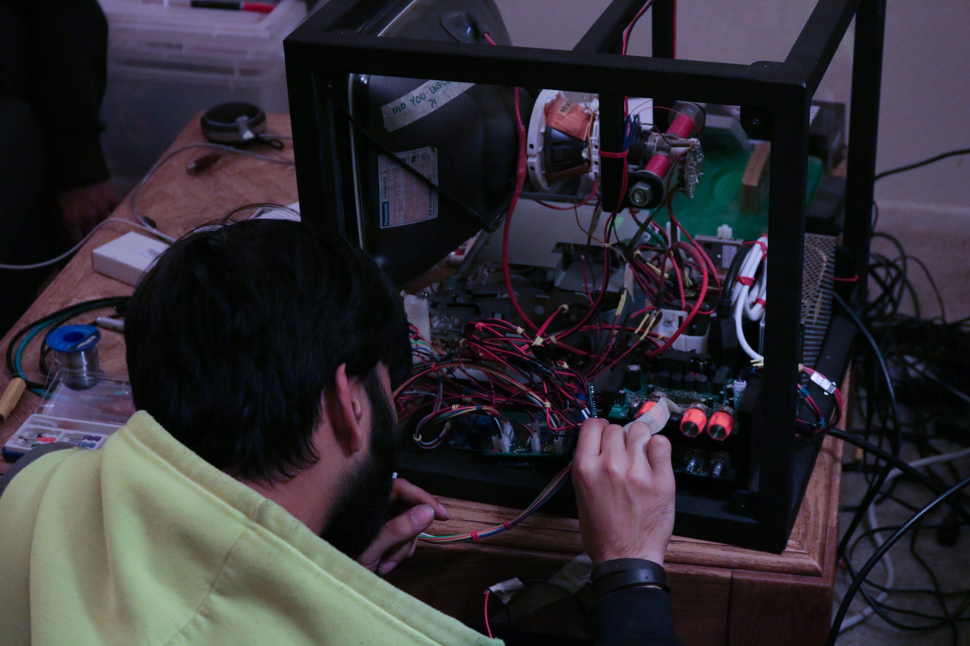
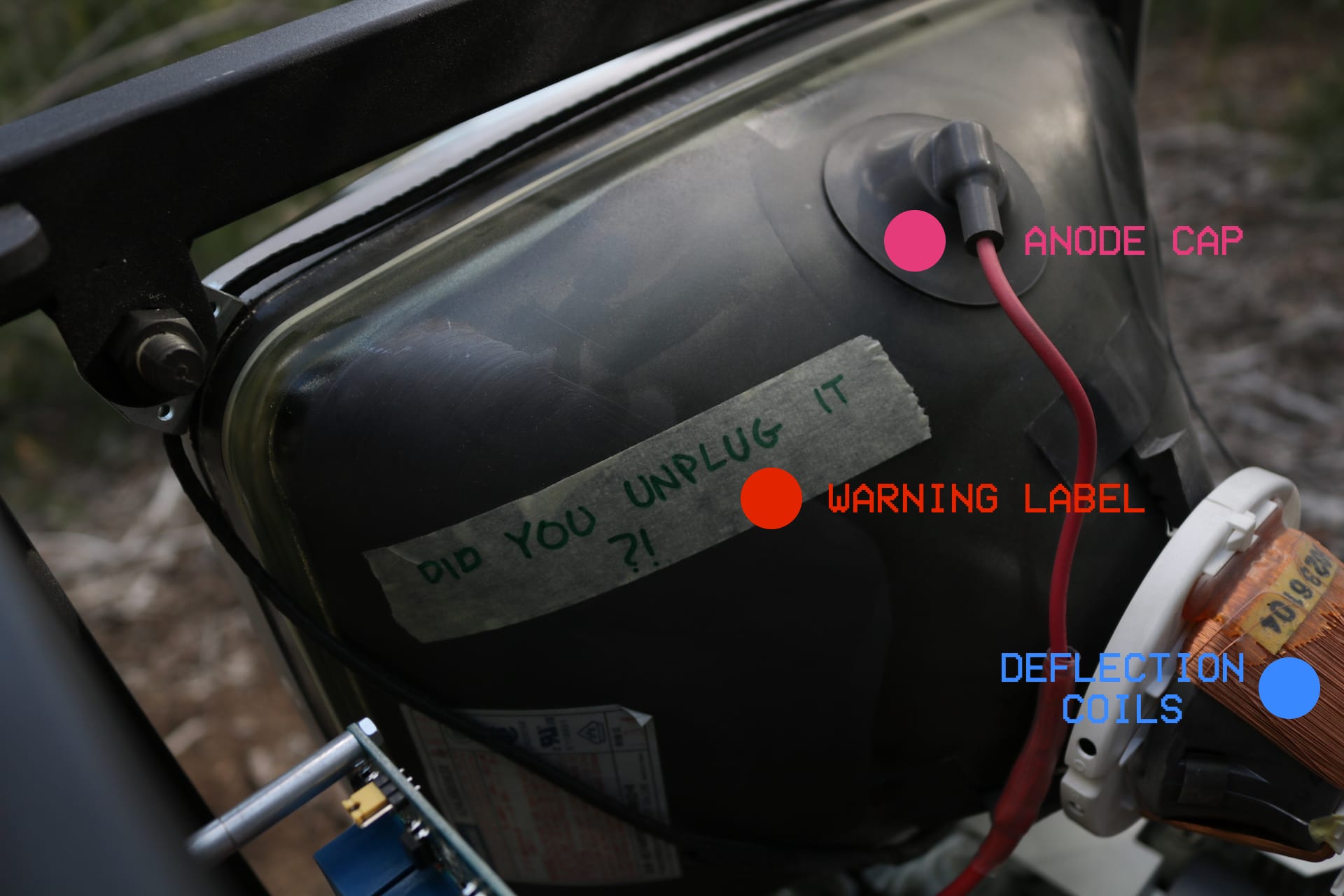
One of the most important safety measures I take on every CRT I have ever opened is to leave yourself a number of safety warnings. Before opening or working on a CRT, always make sure the television has been unplugged! I like to put a ‘DID YOU UNPLUG IT?’ label on all CRT Tubes when I first open them, as well as on the power cord itself. Labelling CRT power cords prevent frustrations when inspecting a well hidden power strip to unplug a television.
If you plan on working on a CRT, it is a very good idea to make yourself a dedicated discharge tool instead of reaching for the nearest flathead screwdriver. If you have access to a machine shop, it is advisable to drill and tap a hole with a set screw to attach your grounding wire securely to your screwdriver.
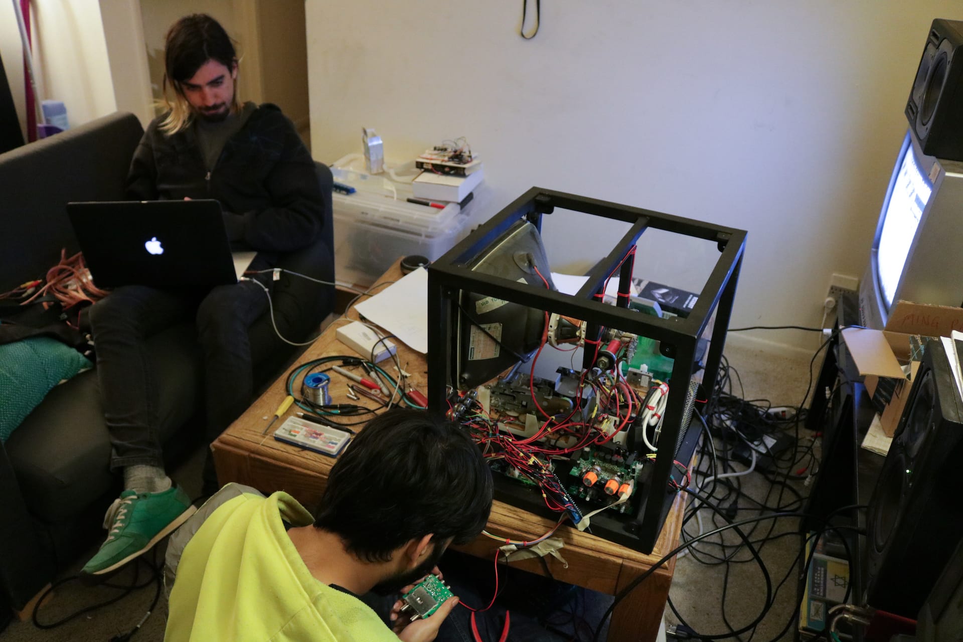
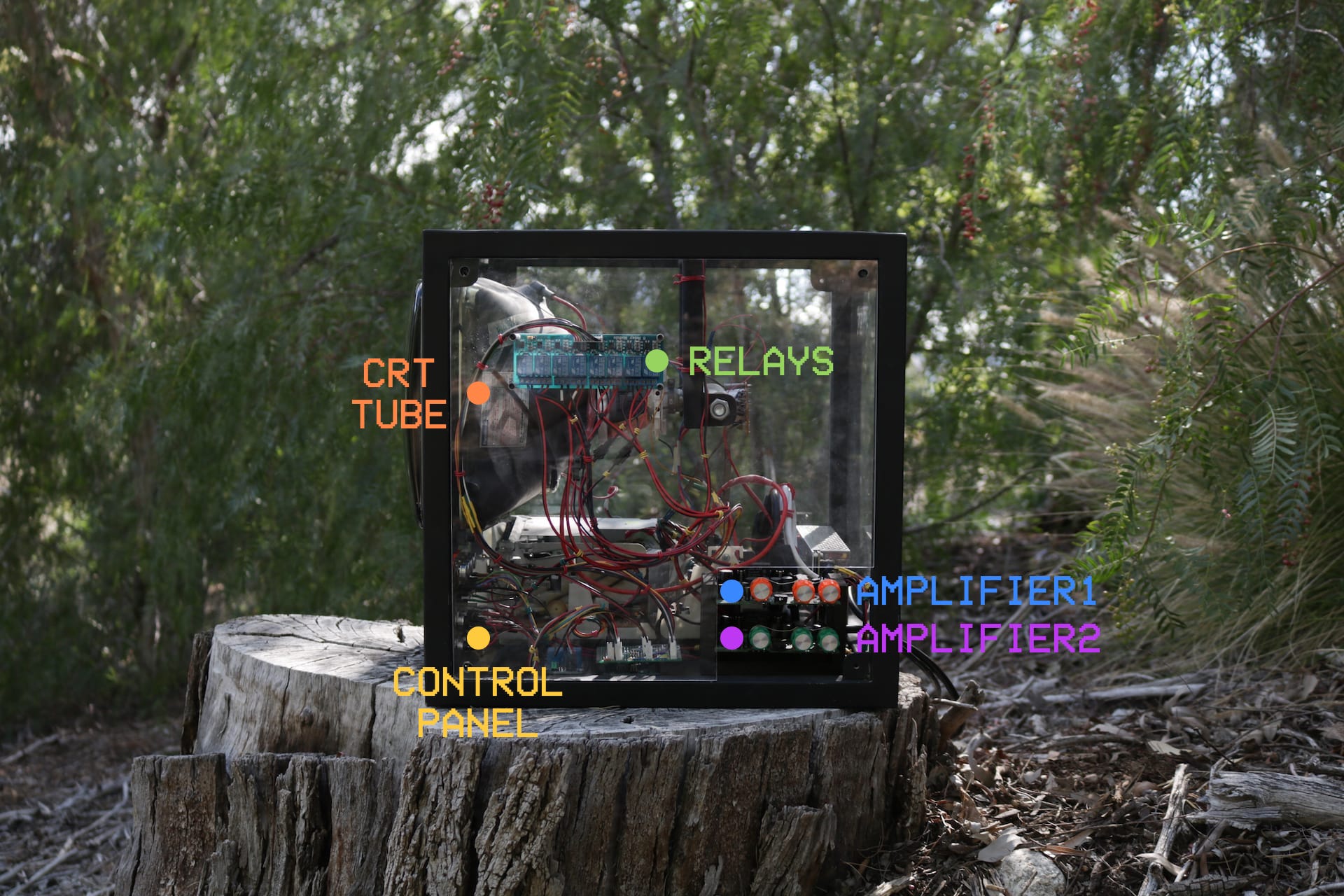
APVTV Construction
APVTV is a highly modified and de-constructed CRT television, which has been re-housed in a welded steel frame, with transparent acrylic panels so that the internals of the CRT are clearly visible. The donor CRT television was a 14" Magnavox from 2004 with built in VHS player that I purchased from Goodwill.
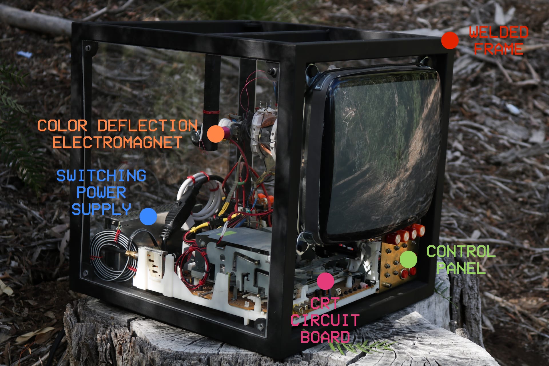
COLOR DEFLECTION ELECTROMAGNETS
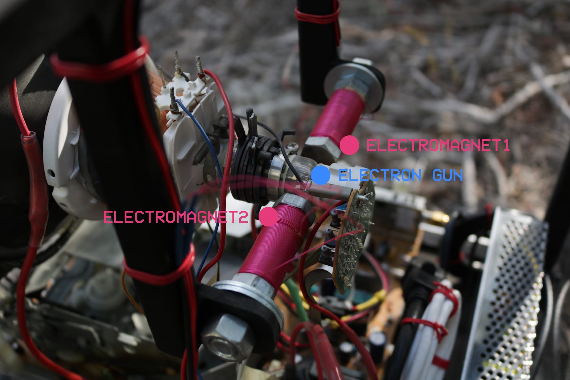
The CRT has been modified to have two custom-made electromagnets located in very close proximity to the CRT's electron gun, and are used for electromagnetic color deflection. These electromagents diverge the RED GREEN and BLUE electron beams, and create color separation effects.
The electromagents are driven by a Pyle 100 watt amplifier originally designed for use with speakers. The electromagnets were hand wound onto core made of a 3/8 inch steel bolt, using the shoulder of the bolt as a guide for wrapping the layers of magnetic wire.
If making your own electromagnets, be sure to use magnet wire, as it is a great deal thinner and more ductile than general purpose stranded wire. When winding the coils of your electromagnet, be sure to periodically test the resistance of the coil using a multimeter, and keep adding wire till you are in the 4 to 8 ohm range - the resistance of an average speaker coil.
APV TV Block Diagram
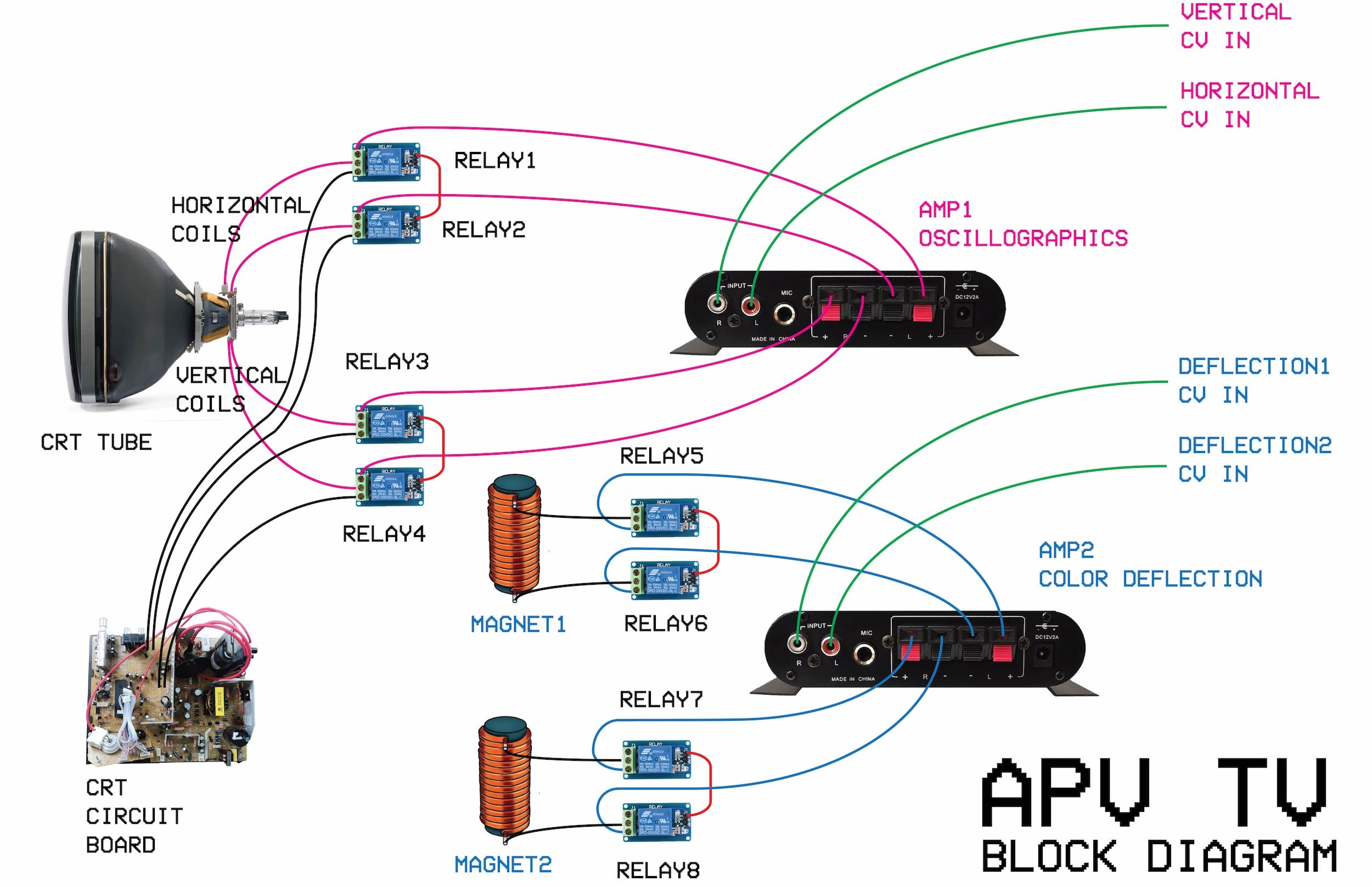
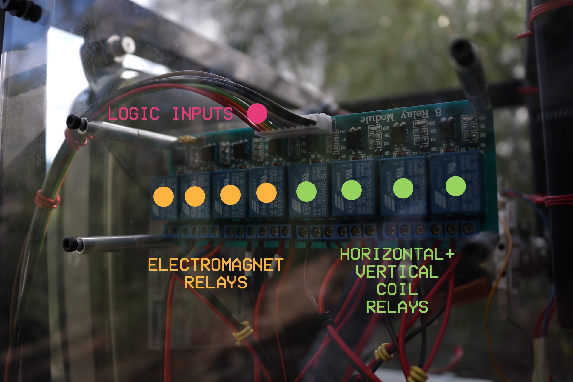
Routing using Relays
When using relays to control the routing of signals inside a turned-on CRT, it is EXTREMELY important to maintain very good isolation between the microcontroller and the CRT's higher voltage signals. Having improper isolation between these two parts of the circuit can result in extreme stability issues - microcontroller crashing and resetting itself every few seconds, to the CRT shutting itself off immidiately as the relays are used.
It is important to note that this technique of re-routing the CRT's internal signals while it is turned on is a very dangerous, violent and sometimes very unpredictable. Any damage or loss of life caused to the CRT, your electronics, your body or anything else as a result of using this technique is to be expected and is not advised to anyone at any time.
Notes on Re-Wiring a CRT Television
When embarking on a CRT re-housing project like APV TV, it is important to find a way to disconnect the picture tube from the control circuit board. I chose to use inline 2-pin and 3-pin Molex connectors spliced between all of the connections between the picture tube and its control circuit board.
I used a step-by-step approach, splicing only a couple connections at a time and testing in between splices. Being able to physically separate the picture tube from its control circuit board allowed me space these two things further apart in APV TV's frame, allowing more space for modifications and viewing.
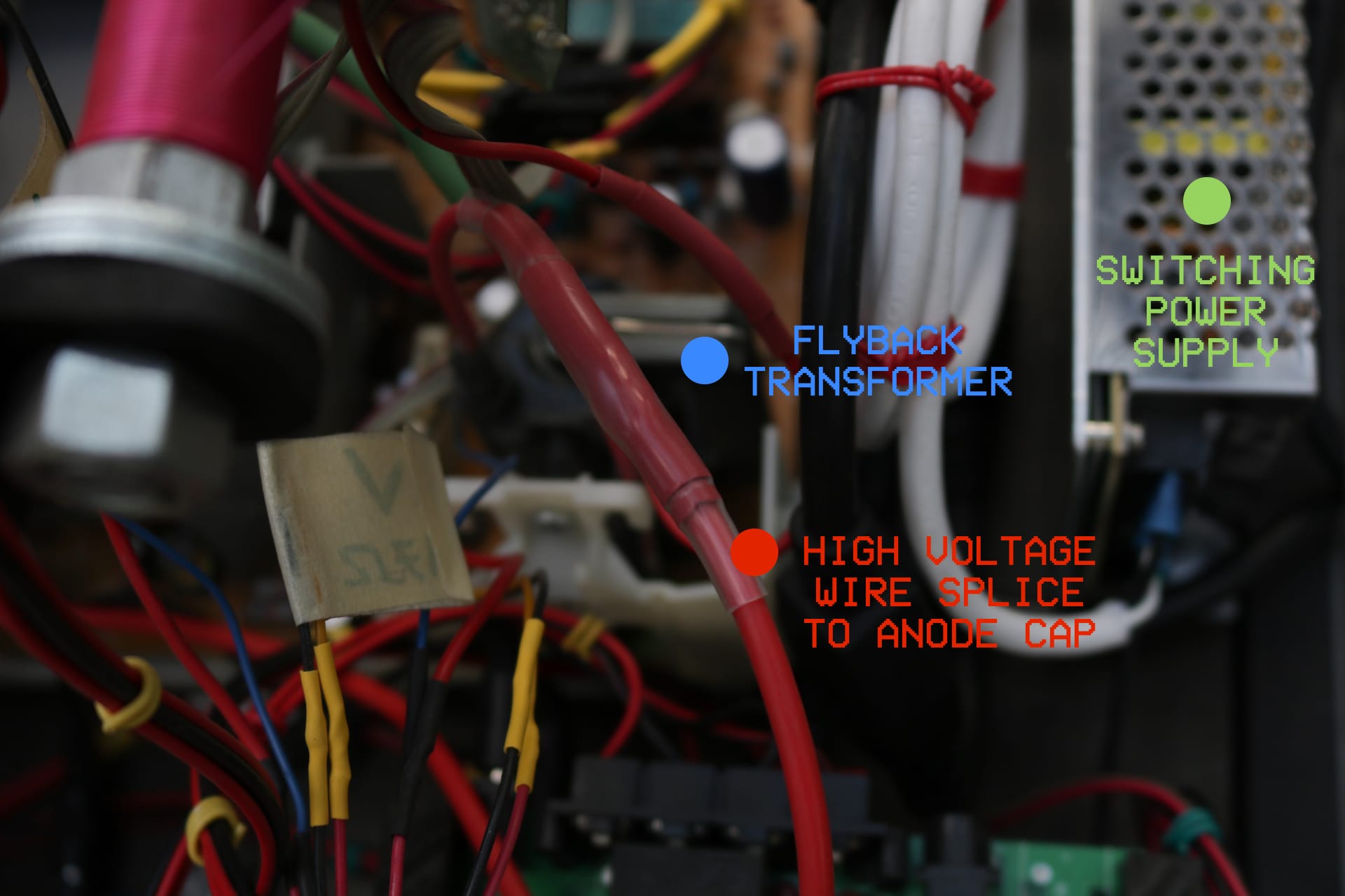
I used 22 AWG stranded wire for all splices, except for the wire connecting the flyback transformer to the anode cap. I extended this wire using 12 AWG stranded silicone wire, with no connector in between. This is the wire that carries the extremely high voltage - 26,000 Volts and above! Be very careful when doing any kind of work on/near the flyback transformer.
This splice is shown below, and I encased the joint in several layers of heatshrink to provide a strong insulation, like the silicone insulation of the wire I was using.
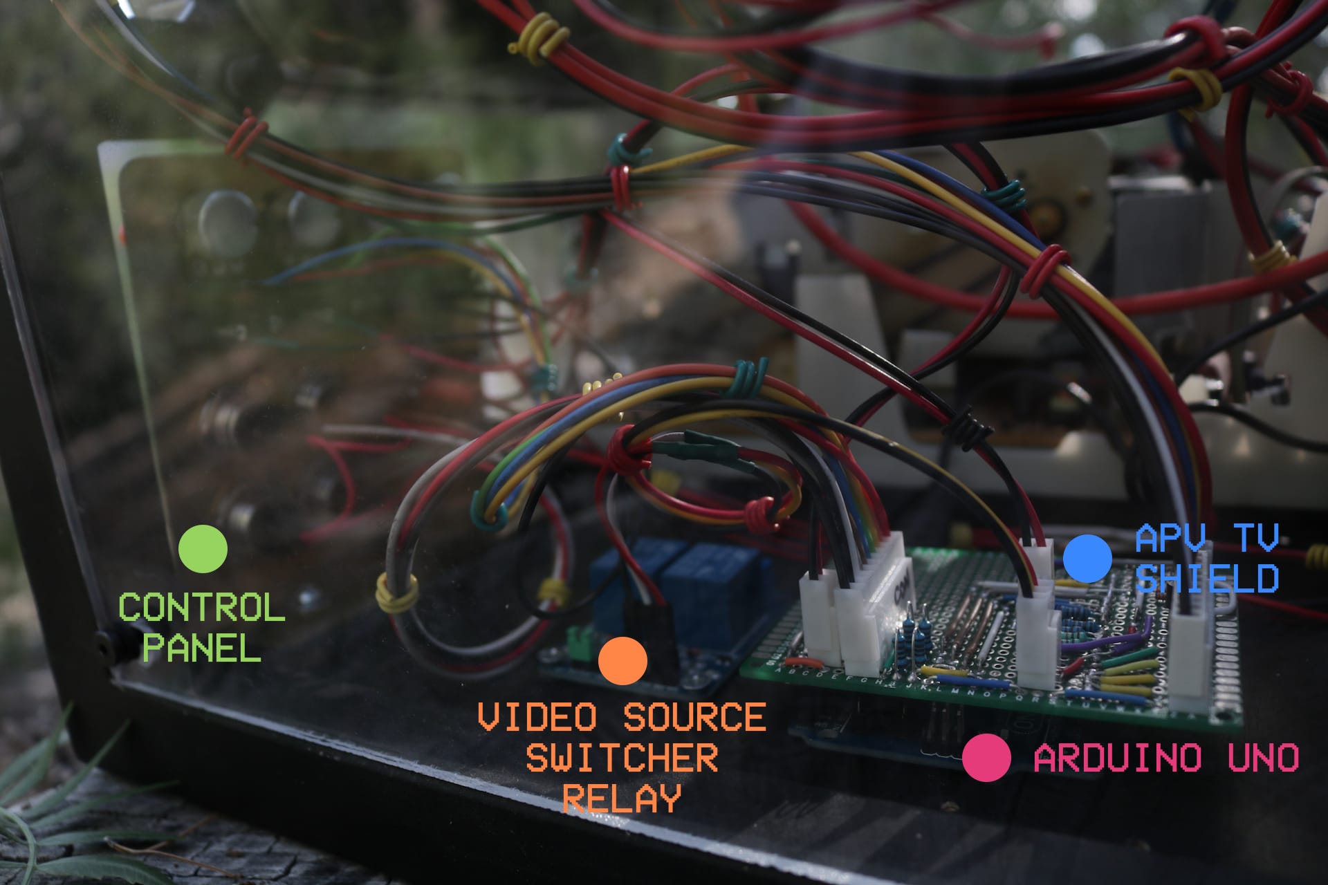
ARDUINO SHIELD
APV TV uses an Arduino microcontroller and a custom made shield to control the input buttons and knobs and composite video output, relay control and control voltage scaling and conditioning.
APV TV Firmware
APVTV contains an Arduino microcontroller board which controls the relays. One logic output from the Arduino switches a pair of relays, for a total of four outputs controlling the TV's deflection signals and electromagnets. Additionally, the microcontroller presents a menu interface on the TV itself, for access to different modes of operation for the relays.
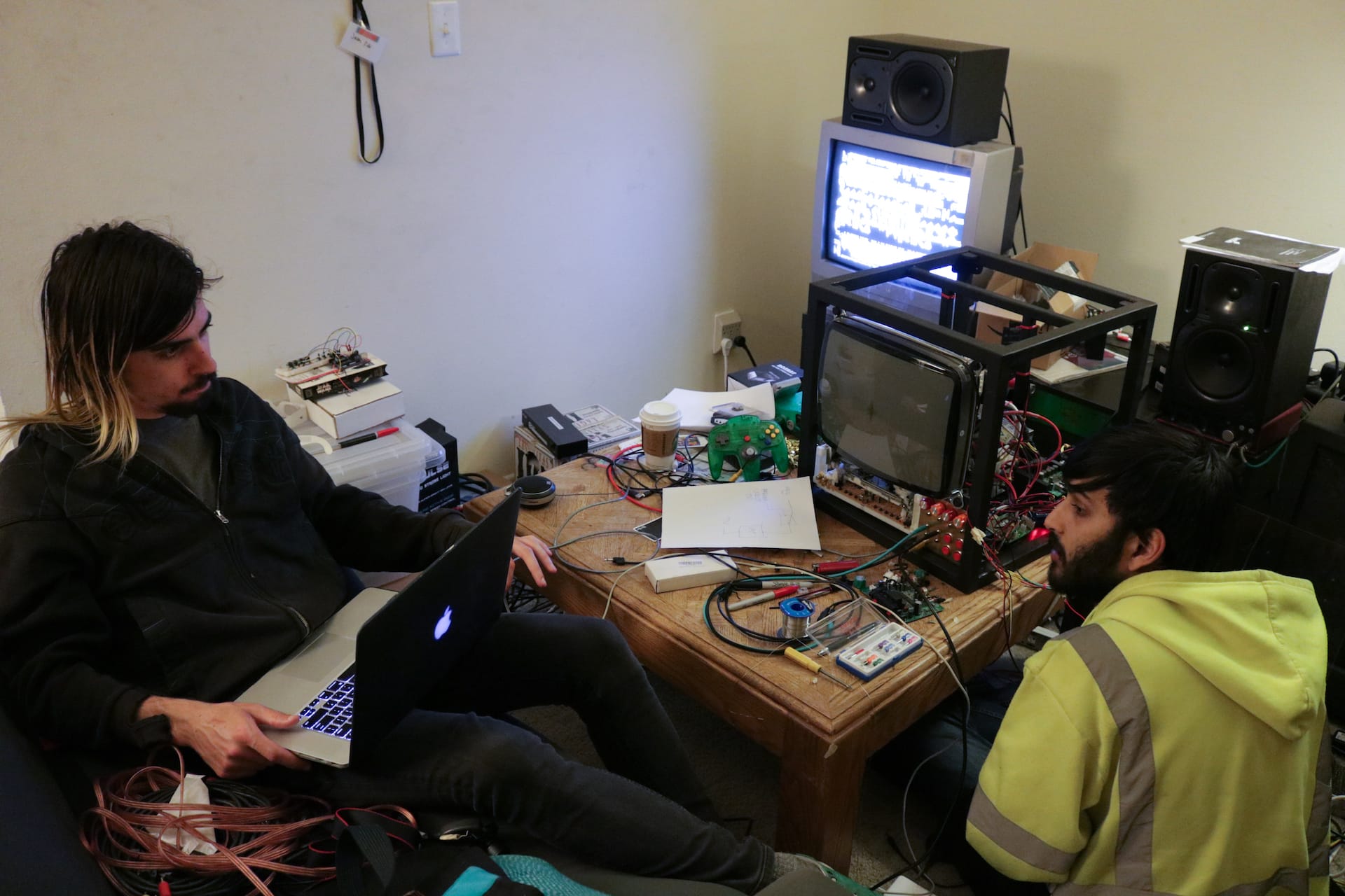
There are two modes that generate rhythmic patterns for the relays using the bytebeat technique. The user can shift and very the speed of the patterns with knobs mounted on the front of APVTV, or using external cntrol voltages. While these modes are active, the bytebeat patterns also corrupt the video memory of the menu system, providing a feedback-like visual element in the absence of external video input.
APVFeedBakE in USE
APVFeedBakE - Shaurjya Banerjee & James Anderson 2018